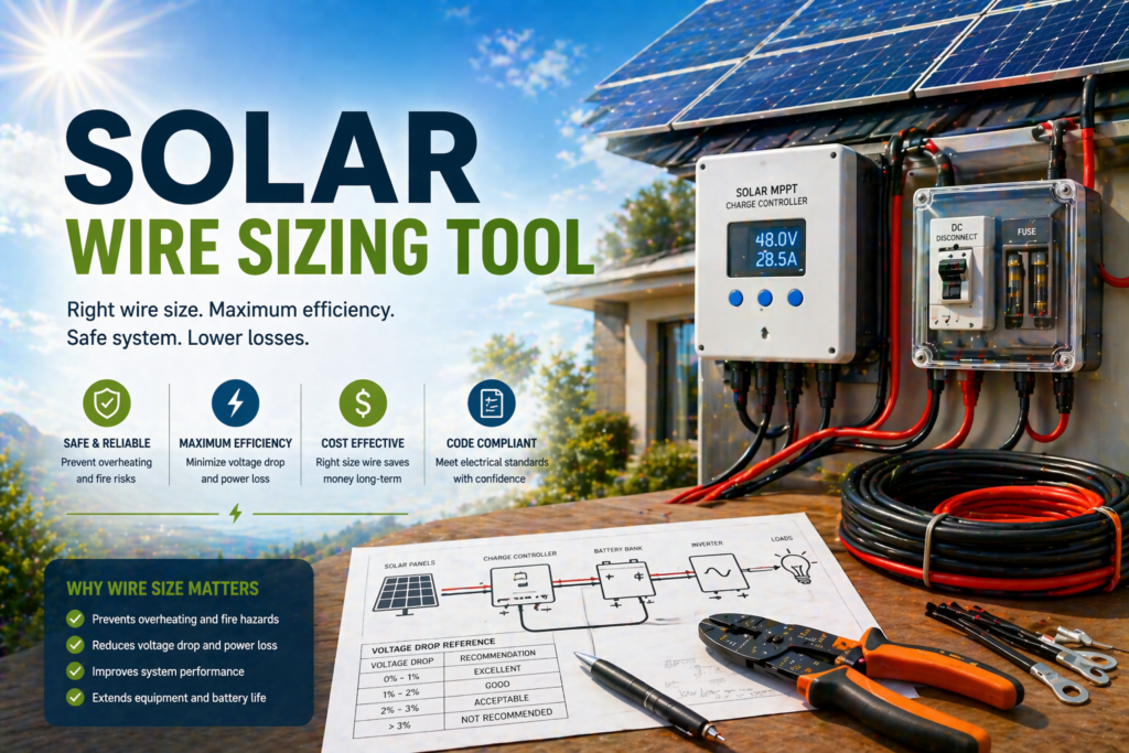
Solar Wire Sizing Tool
Calculate the correct wire size for your solar system based on current, voltage, distance, and acceptable voltage drop. Proper wire sizing ensures safe operation, maximum efficiency, and compliance with electrical standards.
Use Simple Mode for quick sizing or Advanced Mode to model real-world conditions including system voltage, load current, wire length, temperature, and voltage drop limits for accurate, professional-grade results.
How the Solar Wire Sizing Tool Works
A solar wire sizing tool determines the minimum wire gauge needed to safely carry electrical current while keeping voltage drop within an acceptable range. The calculation starts with system current, operating voltage, and total wire run distance. From there, it estimates how much resistance the wire will introduce and whether that resistance causes excessive voltage loss.
Proper wire sizing is critical because undersized wire can overheat, waste power, reduce solar performance, and create safety risks. In advanced mode, the calculation becomes more accurate by accounting for copper or aluminum conductors, temperature correction, allowable voltage drop, and real-world installation conditions. This gives you a planning-grade result instead of a rough guess.
Step 1
Enter the current in amps and the system voltage to define the electrical load the wire must support.
Step 2
Add the total wire run distance so the calculator can estimate resistance and voltage drop over the full circuit length.
Step 3
Set the maximum acceptable voltage drop, usually 2% to 3% for efficient solar system performance.
Step 4
The calculator recommends the wire size needed to safely carry the current and keep voltage loss within range.
Core formula concept: Wire size is based on current load, conductor resistance, total circuit length, and the maximum voltage drop you allow. Lower system voltage and longer runs usually require thicker wire.
Pick the Right Wire Gauge for Your Solar System
NEC-aware planning estimate that checks both voltage drop and ampacity — so you can spot undersized wire before buying parts. Final wiring should be verified against your local electrical code and equipment manuals.
Solar best practice: 2% PV→controller, 3% controller→battery, 3% battery→inverter, 3% inverter→loads
Calculation Breakdown
Wire Gauge Comparison (this run)
| AWG | Resistance | Ampacity (75°C) | Voltage Drop | Status |
|---|
System Notes
Continue Planning After Wire Sizing
Once your wire size is calculated, validate the rest of your system to ensure safe current flow, balanced loads, and efficient performance across your inverter, batteries, and solar panels.
Solar Inverter Size Calculator
Ensure your wiring supports the correct inverter load and surge demands.
Battery Bank Size Calculator
Match your wiring to the correct battery capacity and current flow.
Solar Panel Output Calculator
Verify your system generation to align with wire sizing on the solar side.
Complete Solar System Calculator
Bring all components together to validate your full off-grid setup.
Solar Wire Size Chart for 12V, 24V, and 48V Systems
Use this solar wire size chart as a fast reference for choosing the right wire gauge for solar panels, charge controllers, batteries, and inverters. Wire size depends on system voltage, current, cable distance, and acceptable voltage drop. For the most accurate result, use the solar wire size calculator above and use this chart to double-check common off-grid solar wiring setups.
| System Voltage | Current Load | One-Way Distance | Recommended Wire Size | Typical Use |
|---|---|---|---|---|
| 12V | 10A | Up to 10 ft | 12 AWG | Small panel to charge controller |
| 12V | 20A | Up to 10 ft | 8 AWG | Small battery or controller wiring |
| 12V | 40A | Up to 10 ft | 4 AWG | Battery to inverter or charge controller |
| 24V | 10A | Up to 20 ft | 12 AWG | Panel string wiring |
| 24V | 30A | Up to 15 ft | 8 AWG | Charge controller to battery |
| 24V | 50A | Up to 10 ft | 6 AWG | Medium inverter feed |
| 48V | 10A | Up to 40 ft | 12 AWG | Higher-voltage panel runs |
| 48V | 30A | Up to 25 ft | 10 AWG | Larger solar array wiring |
| 48V | 60A | Up to 15 ft | 6 AWG | Larger battery or inverter connection |
Important Safety Note
This chart is a general solar wire size guide, not a replacement for electrical code, fuse sizing, breaker sizing, or professional installation advice. Always verify wire ampacity, insulation rating, voltage drop, and local code before wiring a solar power system.
Best Practice
If your wire run is long, your current is high, or your voltage is low, move up to a thicker wire size. A 12V solar system usually needs heavier wire than a 24V or 48V system because current is higher at the same wattage.
How to Use This Solar Wire Size Chart
- Choose your system voltage — 12V, 24V, or 48V.
- Estimate your current load in amps.
- Measure the one-way wire distance from the solar panel, controller, battery, or inverter.
- Select the recommended AWG size from the chart.
- Use the calculator above for a more exact solar wire size based on voltage drop and real system inputs.
How To Use This Solar Wire Sizing Tool
Use this solar wire sizing tool to determine the correct wire size for your solar system to ensure safe operation and minimal power loss. Follow these steps to get an accurate result.
Step 1: Enter Current (Amps)
Input the total current your system will carry. This is typically based on your load or solar system output.
Step 2: Enter System Voltage
Input your system voltage (12V, 24V, 48V, etc.). Lower voltages require thicker wire due to higher current.
Step 3: Enter Wire Distance
Enter the total wire length of the circuit. Longer distances increase resistance and voltage drop.
Step 4: Set Voltage Drop Limit
Choose the maximum allowable voltage drop. Typically 2%–3% is recommended for efficient solar systems.
Using Advanced Mode (Recommended)
Advanced Mode allows you to model real-world conditions such as wire material and system variations for a more precise recommendation.
- Select copper or aluminum wiring
- Adjust voltage and current precisely
- Model longer distances accurately
- Apply realistic voltage drop limits
Simple Mode
Best for quick wire sizing based on standard inputs.
Advanced Mode
Best for detailed system planning and accurate real-world results.
Best Practice: Always choose a slightly larger wire size than the minimum recommendation to improve efficiency and ensure long-term safety.
Did You Know
Low Voltage Systems Need Thicker Wire
A 12V solar system often needs much larger wire than a 48V system carrying the same power because lower voltage means higher current.
Wire Distance Matters More Than Most People Think
Even a modest current can cause major voltage drop if the wire run is long. Distance is one of the biggest factors in solar wire sizing.
Undersized Wire Wastes Solar Power
If wire is too small, some of your solar energy is lost as heat before it ever reaches the battery bank, charge controller, or inverter.
Safe Ampacity and Voltage Drop Are Not the Same
A wire may safely carry the current without overheating, but still be too small for efficient solar performance if voltage drop is excessive.
Key Insight: The best solar wire size is not just the smallest wire that works. It is the size that keeps your system safe, efficient, and reliable over the full wire run.
Results Interpretation
Your result from using this solar wire sizing tool will provide the recommended wire gauge required to safely carry the electrical current while keeping voltage drop within your selected limit. This ensures your solar system operates efficiently and safely.
Wire Gauge (AWG)
This is the recommended wire size needed to safely handle the current without overheating or causing excessive resistance.
Voltage Drop
Voltage drop represents energy lost through the wire. Keeping this low ensures maximum solar performance and system efficiency.
Safety Margin
Using a slightly larger wire than required improves system safety, reduces heat, and minimizes long-term efficiency losses.
Sizing Guide:
• 10–8 AWG: Small systems, short runs, low current
• 6–4 AWG: Medium systems, moderate distance
• 2 AWG and larger: High current, long distances, off-grid systems
If your system uses low voltage (12V or 24V), expect to use larger wire sizes due to higher current flow.
Example Calculation
This example demonstrates how to calculate the correct solar wire size using current, voltage, distance, and allowable voltage drop.
System Inputs
Current: 30 Amps
Voltage: 12V
Distance: 60 ft
Voltage Drop: 3%
Voltage Drop Concept
Lower voltage systems require thicker wire because current increases for the same power level.
Goal
Select a wire size that keeps voltage drop below 3% while safely handling the current.
Step-by-Step Breakdown
Step 1: Determine current and voltage
30A at 12V creates a high current load relative to voltage.
Step 2: Factor in distance
60 ft wire run increases resistance and voltage drop.
Step 3: Apply voltage drop limit
Max allowable drop = 3%
Step 4: Result
Recommended wire size: 4 AWG (or larger for safety margin)
Recommended Wire
Voltage Drop Limit
Current Load
Real-World Tip: For low voltage systems like 12V, always consider using thicker wire than the minimum to improve efficiency and reduce heat buildup.
Expert Tips
Correct wire sizing is critical for both safety and efficiency. These expert-level tips help ensure your solar wiring system performs reliably under real-world conditions.
Always Oversize Wire Slightly
Using a slightly larger wire than required reduces resistance, improves efficiency, and increases safety margins.
Keep Voltage Drop Low
Aim for 2–3% voltage drop or less to maintain optimal system performance and reduce energy loss.
Use Copper When Possible
Copper wiring has lower resistance than aluminum, allowing for smaller wire sizes and better efficiency.
Shorten Wire Runs
Reducing wire length minimizes voltage drop and allows for smaller wire sizes.
Advanced Considerations
- Factor in temperature when sizing wire
- Consider conduit fill and insulation type
- Account for continuous load conditions
- Follow local electrical codes and standards
- Use proper connectors and terminations
Ideal Voltage Drop
Best Conductor
Safer Option
Expert Insight: Proper wire sizing improves efficiency, reduces heat, and ensures your solar system operates safely for years to come.
Comparison Table
This table shows how current, voltage, and distance affect wire size requirements in solar systems.
Key Insight: Lower voltage systems require thicker wire due to higher current. Increasing system voltage can significantly reduce wire size requirements.
Visual Insight
Wire size increases significantly with higher current and longer distances, especially in lower voltage systems. This visual helps illustrate how quickly requirements scale.
Wire Size Growth by Load & Distance
Low Load / Short Distance
Moderate Load
High Load / Long Distance
Extreme Conditions
Current Impact
Higher current dramatically increases wire size requirements due to increased resistance and heat generation.
Distance Impact
Longer wire runs increase resistance, requiring thicker wire to maintain efficiency and prevent voltage loss.
Planning Insight: Increasing system voltage is one of the most effective ways to reduce wire size requirements and improve overall system efficiency.
Planning Advice
Proper wire planning ensures your solar system runs efficiently, safely, and reliably over time. Use these guidelines to design wiring that performs under real-world conditions.
Plan for Worst Case
Always size wire based on maximum load and longest distance to ensure performance under peak conditions.
Minimize Distance
Shorter wire runs reduce voltage drop and allow for smaller wire sizes, improving efficiency and lowering cost.
Use Proper Voltage
Higher system voltage reduces current, allowing for smaller wire sizes and better overall system efficiency.
Choose Quality Materials
High-quality copper wiring and proper insulation improve performance, durability, and long-term reliability.
Common Wiring Mistakes
- Using wire that is too small for the current load
- Ignoring voltage drop over long distances
- Not accounting for real-world conditions
- Using low-quality or incorrect wire types
- Failing to follow electrical codes
Ideal Voltage Drop
Best Material
Higher Efficiency
Final Advice: Proper wire sizing is one of the most important aspects of a solar system. It directly impacts safety, efficiency, and long-term performance.
Key Expansion Insights
What size wire do I need for solar panels?
The correct wire size depends on current, voltage, distance, and acceptable voltage drop. Lower voltage systems and longer wire runs typically require thicker wire to maintain efficiency and safety.
How do I calculate solar wire size?
Solar wire size is calculated using current, wire length, system voltage, and voltage drop limits. Accurate sizing ensures minimal energy loss and safe operation.
What is voltage drop in solar systems?
Voltage drop is the reduction in voltage as electricity travels through a wire. Excessive voltage drop reduces system efficiency and wastes solar energy.
Does wire length affect solar performance?
Yes, longer wire runs increase resistance and voltage drop, which can reduce system efficiency. Proper wire sizing compensates for this effect.
Copper vs aluminum wire for solar systems?
Copper wire is more efficient and requires smaller sizes, while aluminum is lighter and less expensive but typically requires larger gauges to achieve the same performance.
Correctly Size Solar Wire and Avoid Voltage Loss, Overheating, and Unsafe Wiring
Twenty practical answers on AWG, voltage drop, copper vs aluminum, NEC 690.8, ampacity derating, and why a 12V long run eats so much copper. Built around practical planning math, with final wiring decisions verified against local code.
Wire Sizing Basics
Q1 – Q4What size wire do I need for solar panels?
It depends on three numbers: current (amps), system voltage, and one-way wire length. The right gauge satisfies two NEC requirements simultaneously — voltage drop AND ampacity. For a system-specific result, use the Solar Wire Size Calculator. Here’s a quick-reference for typical 12V/24V/48V solar runs at 3% target drop:
| Run | Amps | Voltage | Length | Wire (Copper) |
|---|---|---|---|---|
| 100W panel → controller | 6 A | 24 V | 20 ft | 14 AWG |
| 400W array → controller | 10 A | 48 V | 50 ft | 12 AWG |
| Controller → 12V battery | 30 A | 12 V | 10 ft | 8 AWG |
| 3000W inverter → 12V battery | 250 A | 12 V | 6 ft | 4/0 AWG |
| 3000W inverter → 48V battery | 62 A | 48 V | 6 ft | 6 AWG |
Notice that the same 3000W inverter needs 4/0 AWG on 12V but only 6 AWG on 48V — that’s the magic of higher voltage.
What’s the exact formula for solar wire sizing?
Two formulas — voltage drop AND ampacity — and you must pass both. The Solar Wire Size Calculator handles both checks automatically.
Example: a 30A circuit at 12V over 10 ft of 6 AWG copper (R = 0.491 Ω/1000ft):
- VD = 2 × 10 × 30 × 0.491 ÷ 1000 = 0.295 V
- VD% = 0.295 ÷ 12 = 2.45% ✓ under 3%
- Required ampacity = 30 × 1.25 = 37.5 A (DC continuous) — 6 AWG is rated 65 A ✓
What’s the difference between AWG and mm²?
AWG (American Wire Gauge) is the US standard; mm² (cross-sectional area) is metric. They describe the same wire, just with different numbers. Smaller AWG = larger wire (counterintuitive — 4 AWG is bigger than 14 AWG).
| AWG | mm² | Diameter (in) | Diameter (mm) | Typical Use |
|---|---|---|---|---|
| 14 AWG | 2.08 | 0.064″ | 1.63 mm | Low-current panel runs |
| 12 AWG | 3.31 | 0.081″ | 2.05 mm | Single panel ≤15A |
| 10 AWG | 5.26 | 0.102″ | 2.59 mm | Small array → controller |
| 8 AWG | 8.37 | 0.129″ | 3.26 mm | 30A circuit, short run |
| 6 AWG | 13.30 | 0.162″ | 4.12 mm | Mid-size controller→battery |
| 4 AWG | 21.15 | 0.204″ | 5.19 mm | Large 12V controller→battery |
| 2 AWG | 33.62 | 0.258″ | 6.54 mm | 2000W inverter on 24V |
| 2/0 AWG | 67.43 | 0.365″ | 9.27 mm | 3000W inverter on 12V (short) |
| 4/0 AWG | 107.20 | 0.460″ | 11.68 mm | 5000W+ inverter on 12V |
What happens if my wire is too small?
Three failure modes, in escalating order of severity:
- Energy loss as heat (I²R) — power literally radiates from the wire instead of reaching your battery. A 100W panel with 5% wire loss delivers only 95W to the controller.
- Voltage starvation — the device at the end gets less voltage than expected. Inverters cut out, MPPT controllers under-charge, lights dim, motors burn out from low voltage.
- Insulation melt and fire — when wire heats above its insulation rating (60/75/90°C), the jacket softens, then chars, then ignites surrounding material. This is the #1 cause of DIY solar fires.
Voltage Drop & Distance
Q5 – Q8How much voltage drop is acceptable in a solar system?
Industry standard targets, in order of where the energy moves through your system:
| Circuit | Target | Why |
|---|---|---|
| PV array → Charge controller | ≤ 2% | Every lost volt = lost MPPT efficiency |
| Charge controller → Battery | ≤ 3% | Voltage drop confuses charger end-of-charge logic |
| Battery → Inverter | ≤ 3% | Inverter cuts out near low-voltage threshold |
| Inverter → AC loads | ≤ 3% | NEC recommendation for branch circuits |
| Total system end-to-end | ≤ 5% | NEC 210.19 hard limit for combined drop |
Why does distance matter so much for wire sizing?
Voltage drop is linear with distance — double the run, double the drop. The math counts the round trip (current goes out one wire and returns on the other), so a 50 ft “one-way” run is actually 100 ft of resistive copper.
| Length (one-way) | 30A @ 12V on 8 AWG | VD% | Wire needed |
|---|---|---|---|
| 5 ft | 0.23 V | 1.95% | 8 AWG ✓ |
| 10 ft | 0.47 V | 3.89% | 6 AWG |
| 25 ft | 1.17 V | 9.72% | 2 AWG |
| 50 ft | 2.33 V | 19.45% | 1/0 AWG |
| 100 ft | 4.67 V | 38.9% | 4/0 AWG (still over!) |
Why do low voltage systems need thicker wire?
Power = Volts × Amps. To deliver the same wattage at lower voltage, you need proportionally more amps. And voltage drop scales with current, so amps drive wire size — not power.
| System | 3000W draw | Wire (10 ft) | Cost (Cu) |
|---|---|---|---|
| 12 V | 250 A | 4/0 AWG | ~$80 |
| 24 V | 125 A | 1 AWG | ~$25 |
| 48 V | 62 A | 6 AWG | ~$8 |
| 120 V (AC) | 25 A | 10 AWG | ~$3 |
The relationship is the inverse-square — doubling voltage cuts copper area by 4×. Going from 12V to 48V saves you ~10× on wire costs and weight.
Should I size for nominal voltage or actual voltage?
Always use nominal voltage for your VD% calculation — it’s the worst-case scenario. A “12V” system actually runs 11.5–14.4V depending on charge state, but sizing assumes 12V because at low charge the voltage is most fragile and inverter cutouts trigger.
| System | Nominal | Min (Disconnect) | Max (Bulk) |
|---|---|---|---|
| 12V LiFePO4 | 12 V | 10 V | 14.4 V |
| 24V LiFePO4 | 24 V | 20 V | 28.8 V |
| 48V LiFePO4 | 48 V | 40 V | 57.6 V |
| 12V Lead-Acid | 12 V | 10.5 V | 14.7 V |
| 24V PV (Voc max) | 24 V | — | ~37 V (Voc cold) |
For PV → controller, use the panel’s Vmp (voltage at max power) for VD math. For controller → battery and battery → inverter, use the battery’s nominal voltage.
AWG, Copper & Aluminum
Q9 – Q12Is copper better than aluminum for solar wiring?
For most off-grid and residential solar work — yes, copper wins. Aluminum has a niche for very long, heavy runs where weight and cost matter, but it has serious tradeoffs.
| Property | Copper | Aluminum |
|---|---|---|
| Resistance | Baseline | 1.6× higher (need 2 sizes larger) |
| Ampacity per AWG | Baseline | ~78% (one column down) |
| Weight | Baseline | ~50% lighter |
| Cost per foot | Baseline | ~50% cheaper (raw) |
| Cost per amp delivered | Baseline | ~30% cheaper at large sizes |
| Termination difficulty | Easy | Anti-oxidant compound + special lugs required |
| Cold flow / loosening | Stable | Loosens over time, needs re-torquing |
| Corrosion | Moderate | High (galvanic w/ copper terminals) |
What’s the actual resistance of common solar wire?
NEC Chapter 9 Table 8 values, ohms per 1000 ft at 75°C:
| AWG | Copper Ω/kft | Aluminum Ω/kft | Cu Ampacity (75°C) | Al Ampacity (75°C) |
|---|---|---|---|---|
| 14 | 3.140 | 5.024 | 20 A | — |
| 12 | 1.980 | 3.168 | 25 A | 20 A |
| 10 | 1.240 | 1.984 | 35 A | 30 A |
| 8 | 0.778 | 1.245 | 50 A | 40 A |
| 6 | 0.491 | 0.786 | 65 A | 50 A |
| 4 | 0.308 | 0.493 | 85 A | 65 A |
| 2 | 0.194 | 0.310 | 115 A | 90 A |
| 1/0 | 0.122 | 0.195 | 150 A | 120 A |
| 2/0 | 0.0967 | 0.155 | 175 A | 135 A |
| 4/0 | 0.0608 | 0.0972 | 230 A | 180 A |
These are the numbers the calculator uses. Resistance climbs about 0.4% per °C above 75°C, so hot ambient air requires derating.
What insulation type should I use for solar wire?
The wrong insulation can cut your ampacity in half. For solar applications:
| Type | Temp Rating | UV / Wet | Best For |
|---|---|---|---|
| PV Wire (USE-2/RHW-2) | 90 °C | UV-stable, sunlight resistant | Outdoor exposed PV array runs |
| THHN/THWN-2 | 90 °C / 75 °C wet | Conduit only | In-conduit DC and AC |
| USE-2 | 90 °C | Direct burial OK | Underground feeders |
| UF-B | 60 °C | Direct burial OK | Branch circuits, low-temp only |
| NM-B (Romex) | 60 °C | Indoor dry only | NEVER for outdoor solar |
| Welding cable | 105 °C typical | Not NEC-listed for permanent | Battery jumpers only |
Should I use stranded or solid wire for solar?
Almost always stranded. Stranded copper handles vibration, flexes around corners, and terminates better on heavy lugs.
| Wire Type | Best Use | Avoid |
|---|---|---|
| Solid (1 strand) | Tight conduit pulls, fixed branch circuits | Battery cables, vibration-prone runs |
| Stranded class B (7–19 strands) | Most solar PV runs, in-conduit feeders | — |
| Stranded class K (fine, ~133 strands) | Battery interconnects, inverter feeds, RV/boat | — |
| Welding cable (fine strand, no NEC listing) | Temporary or battery jumper kits | Permanent installs without re-listing |
For battery and inverter cables, fine-strand (class K) makes a noticeable difference in flexibility and resistance to fatigue cracks. Pair with tinned copper lugs and proper crimp tools — never twist-and-tape.
NEC Code & Safety
Q13 – Q16What is the NEC 690.8 1.56× rule?
NEC Article 690.8 requires solar PV circuits to be sized for 156% of the panel’s rated current (Isc). The 1.56× factor breaks down as:
The continuous-load 1.25× is the standard NEC factor for any circuit running 3+ hours. The irradiance 1.25× accounts for clouds focusing extra sunlight onto the array (yes, briefly more than 1000 W/m²).
| Panel Isc | Required Wire Ampacity | Min Wire (Cu, 75°C) |
|---|---|---|
| 6 A (100W panel) | 9.4 A | 14 AWG |
| 10 A (300W panel) | 15.6 A | 14 AWG |
| 20 A (2-panel parallel) | 31.2 A | 10 AWG |
| 40 A (4-panel parallel) | 62.4 A | 6 AWG |
| 80 A (8-panel parallel) | 124.8 A | 1 AWG |
This is the minimum. Voltage drop usually drives you to a larger size on long runs.
What is wire derating and when does it apply?
Two derates apply to most solar runs:
1. Ambient temperature derate (NEC 310.15(B)(2)(a)) — wire ampacity drops as ambient air heats up:
| Ambient Temp | 60°C insulation | 75°C insulation | 90°C insulation |
|---|---|---|---|
| Up to 86°F (30°C) | ×1.00 | ×1.00 | ×1.00 |
| 87–95°F (31–35°C) | ×0.91 | ×0.94 | ×0.96 |
| 96–104°F (36–40°C) | ×0.82 | ×0.88 | ×0.91 |
| 105–113°F (41–45°C) | ×0.71 | ×0.82 | ×0.87 |
| 114–122°F (46–50°C) | ×0.58 | ×0.75 | ×0.82 |
| 123–131°F (51–55°C) | — | ×0.67 | ×0.76 |
2. Conduit fill derate (NEC 310.15(B)(3)(a)) — multiple current-carrying conductors in one conduit can’t shed heat:
| # Conductors | Multiplier |
|---|---|
| 1–3 | ×1.00 |
| 4–6 | ×0.80 |
| 7–9 | ×0.70 |
| 10–20 | ×0.50 |
Multiply both derates: a 6 AWG copper at 65A becomes 65 × 0.88 (104°F) × 0.80 (5 conductors in conduit) = 45.8 A effective.
Do I need a fuse or breaker on every solar wire?
NEC requires overcurrent protection on virtually every conductor in a PV system. The only exceptions are short jumpers between batteries in a single bank.
| Circuit | Protection | Typical Sizing |
|---|---|---|
| PV → Combiner box | String fuses | 1.56 × Isc, rounded up |
| Combiner → Charge controller | DC breaker | 1.25 × controller input |
| Charge controller → Battery | DC breaker / fuse | 1.25 × controller output |
| Battery → Inverter | Class T fuse (within 18″) | Inverter max DC current × 1.25 |
| Inverter → AC panel | AC breaker in panel | Per inverter manual |
| Battery interconnects (same bank) | Not required (single battery bank) | — |
What size lugs and terminals do I need?
Lugs must match BOTH the wire AWG and the terminal stud size. Common matchups:
| Wire | Lug AWG | Common Stud Sizes | Crimp Tool |
|---|---|---|---|
| 14–10 AWG | matching | #10, 1/4″ | Hand crimper |
| 8–6 AWG | matching | 1/4″, 5/16″ | Hammer crimp or hydraulic |
| 4–2 AWG | matching | 5/16″, 3/8″ | Hydraulic ($30–80 tool) |
| 1/0–4/0 AWG | matching | 3/8″, 1/2″ | Hydraulic, 12-ton class |
Mistakes & Best Practices
Q17 – Q20What are the most common DIY solar wiring mistakes?
From most common to most dangerous:
- Sizing on ampacity alone — passing the NEC table doesn’t mean voltage drop is OK. Long runs need bigger wire than the ampacity table suggests.
- Using indoor (NM-B / Romex) wire outdoors — UV destroys the jacket in months, then water ingress, then a short.
- No fuse between battery and inverter — a #1 cause of off-grid fires. Always Class T within 18″ of battery+.
- Mixing copper and aluminum without antioxidant — galvanic corrosion eats the connection in 1–2 years.
- Twisted-and-taped battery cables — high resistance, melts the tape, eventually arcs.
- Undersized lugs — wire is rated 250A but a #10 stud and 4 AWG lug can’t pass it.
- Forgetting NEC 690.8 1.56× — sizing for Isc instead of 1.56 × Isc.
- Reverse polarity — instantly destroys MPPT controllers; happens when red and black get crossed at night.
How do I extend wire if I bought it too short?
Three legitimate methods, in order of professionalism:
- Junction box with terminal blocks — best for permanent indoor extensions. Use a NEMA-rated box outdoors.
- Inline butt-splice connector with adhesive heat-shrink — purpose-made for solar (look for “PV-rated”), waterproof, smaller than a junction box.
- MC4 connector pair — for PV array runs, the cleanest extension method. Just match polarity.
How do I know if my wire is overheating in operation?
The fastest, safest way is an infrared thermometer (~$20). Take readings on the wire jacket about 1 ft from each end after the system has been at full load for 30+ minutes.
| Wire Surface Temp | Status | Action |
|---|---|---|
| Below 95°F | Normal | Nothing needed |
| 95–120°F | Warm but safe | Note for future upgrade |
| 120–140°F | Hot | Reduce load or upsize wire |
| 140–160°F | Approaching insulation limit | Stop load, upsize immediately |
| 160°F+ | DANGEROUS | Disconnect; risk of insulation failure / fire |
Also feel each lug and terminal — they should be the same temperature as the wire. A hot terminal means high resistance from a loose connection or oxidized contact.
What’s the cheapest way to fix a wire that’s too small?
Five options, ranked from least to most expensive:
- Run a parallel conductor — same gauge wire alongside the existing run, bonded at both ends. Two 8 AWG in parallel = roughly equivalent to one 5 AWG. Per NEC, parallel conductors must be #1/0 or larger for permanent installs in many cases — check local code.
- Reduce the load — if a 30A circuit is too much for 12 AWG, reduce loads on it.
- Step up system voltage — moving from 12V to 24V cuts current in half, freeing your existing wire from being the bottleneck. Requires inverter and controller change.
- Move the equipment closer — relocating an inverter from 50 ft to 5 ft from the battery can drop wire size by 4 levels.
- Replace with proper wire — the right answer if loads are fixed and voltage upgrade isn’t viable. Pull-string the new wire alongside, then yank the old.
Run the math for your exact system
Try the interactive Solar Wire Size Calculator — 6 application presets, copper/aluminum, NEC 690.8 + 1.25× factors, temp + bundle derating, and side-by-side gauge comparison.
Open the Solar Wire Size Calculator →Continue Planning After Wire Sizing
Once your wire size is calculated, validate the rest of your system to ensure safe current flow, balanced loads, and efficient performance across your inverter, batteries, and solar panels.
Solar Inverter Size Calculator
Ensure your wiring supports the correct inverter load and surge demands.
Battery Bank Size Calculator
Match your wiring to the correct battery capacity and current flow.
Solar Panel Output Calculator
Verify your system generation to align with wire sizing on the solar side.
Complete Solar System Calculator
Bring all components together to validate your full off-grid setup.