
Solar Wire Size Calculator
Compare preliminary cable sizes, voltage drop and resistive power loss from circuit current (or watts), operating voltage and cable length. Simple mode uses fixed planning assumptions. Advanced mode adds conductor material, insulation and terminal ratings, ambient temperature and conduit grouping. Sizes run from 14 AWG to 750 kcmil, or evaluate actual 1.5–240 mm² copper cables using the stated metric installation model.
This is an educational planning estimate, not wiring approval. It does not select a fuse or breaker, and it does not establish compliance with the electrical rules that apply to your installation.
Jump to the calculator Assumptions and worked example Methodology and limitations
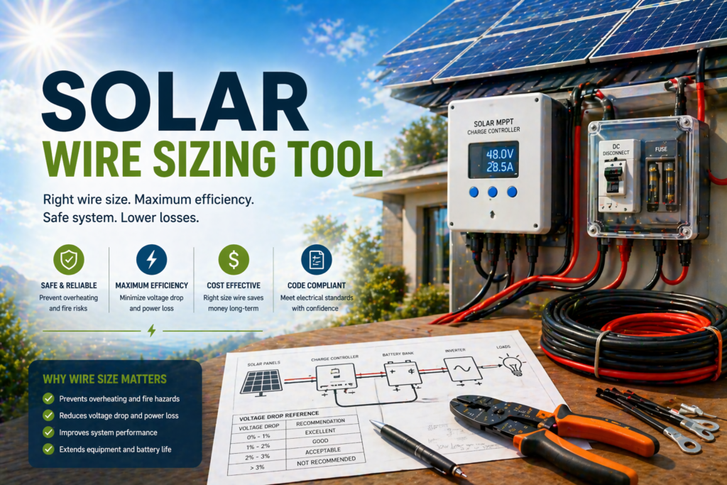
Find a preliminary wire size for your solar circuit
Checks voltage drop and ampacity together, so you can spot undersized cable before buying parts. AWG mode uses NEC Table 310.16 and Chapter 9, Table 8. Metric mode uses independent IEC nominal copper sizes and the stated PVC / method C model below.
Quick start: pick a common run
Metric cable model: copper, IEC class 2, PVC 70 °C, two loaded conductors, clipped direct (method C). Sizes: 1.5–240 mm². AWG material and insulation controls do not apply.
Select these factors for the actual installation. The 1.25 default is an explicit planning allowance. PV uses the same entered allowance; no hidden NEC multiplier is applied.
Calculation breakdown
Size comparison for this run
| Size | Resistance | Max design current | Voltage drop | Status |
|---|
System notes
Helpful equipment
Equipment for Solar Wiring Assessment
These example products are not a cable or protection recommendation based on your results. Voltage-drop calculations alone do not establish safe conductor ampacity, insulation, termination, temperature derating, overcurrent protection or code compliance. Have electrical wiring verified by a qualified professional.
Klein Tools CL390 Digital Clamp Meter
Compare current-measurement capability and safety ratings for professional electrical checks.
Click for the latest price.BOSCH GLM 50 C Laser Distance Measure
Measure approximate cable-route lengths during preliminary site layout.
Click for the latest price.Renogy 200W Monocrystalline Solar Panel
Review PV current and voltage ratings when planning a panel circuit.
Click for the latest price.Victron SmartSolar MPPT 100/50 Controller
Compare controller input and output limits relevant to circuit current planning.
Click for the latest price.This section contains affiliate links. We may earn a commission.
How to use the solar wire size calculator
- Identify the circuit and its design current. A PV string and a battery-to-inverter cable carry very different currents. If you think in watts, the calculator can estimate current at your operating voltage (DC, or AC assuming power factor 1). Use actual equipment current whenever available.
- Enter the operating voltage. For a PV run this is the string Vmp, not the battery voltage, because voltage drop is a percentage of the voltage the circuit actually runs at.
- Enter the one-way cable length. The calculator doubles it for the round trip. Use the unit toggle for feet and °F or meters and °C. The unit toggle also changes the cable model: AWG uses NEC-oriented screening; metric uses the stated IEC method C model. It is not merely a display conversion.
- Choose the circuit type: continuous load, non-continuous load, or PV source circuit. For PV source circuits, enter the applicable Isc in amps; watts cannot be used to calculate Isc.
- Choose a voltage-drop target. A selected percentage is a comparison input, not proof that an installation is suitable.
- Use Advanced mode for aluminum, a different insulation or terminal rating, ambient temperature and conduit grouping. Confirm the actual cable, lugs and installation conditions separately.
- Read both the voltage drop and the ampacity checks. A size that passes one can fail the other.
Voltage-drop and power-loss formulas
Round-trip resistance = conductor resistance per 1,000 ft × 2 × one-way length (ft) ÷ 1,000.
Voltage drop = current × round-trip resistance. Percentage drop = voltage drop ÷ operating voltage × 100. Conductor power loss = current² × round-trip resistance.
The calculator uses tabulated approximate 75 °C DC conductor resistance for a two-conductor round trip, based on NEC Chapter 9, Table 8. It does not model AC reactance, three-phase circuits, voltage-dependent load behavior or connection resistance, so its results describe the stated model rather than the complete circuit. At high inverter current, actual battery voltage can fall below nominal, increasing current; use the inverter manufacturer’s maximum DC input-current specification and lowest operating input voltage for design.
How the preliminary size is selected
The calculator checks sizes from 14 AWG up to 750 kcmil and picks the first one that passes the voltage-drop target and both of these ampacity checks:
- Terminal check. The table ampacity at the limiting temperature column (lower of the selected insulation and terminal columns, with conservative small-conductor protection caps used as a screening limit) must be at least the current × 1.25 for a continuous load, × 1.00 for a non-continuous load, or × 1.5625 for a PV source circuit entered as Isc.
- Derating check. The ampacity in the insulation column, multiplied by the ambient-temperature and conduit-grouping factors, must be at least the current × 1.00, or × 1.25 for a PV source circuit.
These are separate screening checks rather than one compounded derating formula. The stricter check determines the preliminary size. PV exceptions, conductor types and small-conductor protection requirements can alter an actual installation design. Actual terminal ratings, source-circuit rules, continuous-load classification, permitted wiring methods, protective-device selection and adopted code edition must be independently confirmed.
Worked example: 30 A over a 10 ft one-way run at 12 V
Take a continuous 30 A load on copper with a 3% voltage-drop target. The comparison starts at 8 AWG, which has an approximate resistance of 0.778 Ω per 1,000 ft.
- Round-trip length: 2 × 10 = 20 ft.
- 8 AWG resistance: 0.778 × 20 ÷ 1,000 = 0.01556 Ω. Voltage drop: 30 × 0.01556 = 0.4668 V, or 3.89%. That exceeds the 3% target.
- 6 AWG resistance: 0.491 × 20 ÷ 1,000 = 0.00982 Ω. Voltage drop: 30 × 0.00982 = 0.2946 V, or 2.455% (displayed as 2.46%). Resistive loss: 30² × 0.00982 = 8.838 W (displayed as 8.8 W).
- Terminal check for 6 AWG: 30 × 1.25 = 37.5 A against 55 A at the Simple-mode 60 °C terminal assumption (65 A if listed 75 °C terminals are explicitly selected in Advanced mode). The derating check also passes, so the calculator selects 6 AWG copper.
A larger conductor lowers resistance, but voltage drop alone is not enough to approve a cable or a protection device.
What the results mean
Recommended size is the smallest size in the calculator’s table that passes every modeled check. Voltage drop estimates conductor-only voltage loss. Max design current is the largest design current the size supports after both ampacity checks. Power lost is the I²R heat in the two conductors, not a thermal simulation.
If no size from 14 AWG to 750 kcmil passes, the calculator gives no recommendation and says whether current or voltage drop is the limit. Shortening the run or raising the system voltage usually helps most. Metric mode evaluates actual 1.5–240 mm² class 2 copper cables with PVC 70 °C insulation, two loaded conductors and method C (clipped direct). Each size has its own IEC-based resistance and current capacity, with entered ambient/grouping corrections and an explicit current allowance. It does not reuse AWG ratings. Other metric cable types and installation methods are outside this model.
Metric cable model and sources
Metric ampacity uses the C / two PVC loaded-conductor column of Schneider Electric’s IEC 60364 sizing guide (Figure G21). Ambient corrections follow its Figure G12, rounding upward to the next listed ambient band. The grouping factor is entered directly. Maximum class 2 plain-copper resistance at 20 °C comes from LAPP’s IEC 60228 conductor data and is corrected to 70 °C using R70 = R20 × [1 + 0.00393 × 50]. Drop uses the two-wire round trip. Verify cable and terminal ratings separately; there is no automatic fuse or breaker selection.
Installation safety checks beyond this estimate
Simple mode uses copper, 75 °C insulation, a conservative 60 °C terminal assumption, 30 °C ambient and at most three current-carrying conductors. Verify equipment markings before selecting 75 °C or 90 °C terminals. A 90 °C cable rating alone does not authorize 90 °C termination ampacity. The AWG model uses NEC Table 310.16 installation assumptions, not free-air, marine, fine-stranded battery-cable or universal PV-cable ratings. Conduit fill and rooftop exposure are not calculated.
PV uses the entered combined-string Isc for both screening loss and ampacity. Ordinary NEC-oriented PV checks use 1.25 × Isc for maximum current, then a further 1.25 for the unadjusted check (1.5625 × Isc); the corrected-capacity check uses 1.25 × Isc. Equipment-limited circuits, bifacial gain, parallel strings and adopted-code exceptions need separate assessment. Actual operating loss normally uses Imp and operating voltage; Isc and Vmp are not a real simultaneous operating point.
Wire ampacity is not a fuse or breaker rating. Verify conductor protection, equipment limits, DC voltage and interrupting ratings, fault-current withstand, disconnects and source-end protection. Small-conductor screening caps are conservative and do not implement every exception or protective-device rule. In IEC installations, check load/protection/cable coordination (Ib ≤ In ≤ Iz and I2 ≤ 1.45 Iz where applicable), short-circuit withstand and disconnection time.
This tool does not size equipment grounding, bonding, protective earth or grounding-electrode conductors. Do not use earth as the normal return conductor. Grounding and fault paths require separate design. Confirm wet-location, sunlight, mechanical protection, connector compatibility, conductor strand class and manufacturer torque requirements.
Reference checks: Southwire ampacity and protection guidance; Eaton PV conductor-sizing guidance. These manufacturer references do not replace the locally adopted electrical code.
Solar wire sizing questions
Does this calculator choose the correct fuse or breaker?
No. Overcurrent protection is not determined. Fuse or breaker selection depends on the actual circuit, equipment, conductor and installation requirements, and cannot be inferred from a voltage-drop result.
Can I substitute aluminum for copper at the same gauge?
Do not assume they are interchangeable. The calculator uses different resistance and ampacity values for each material, and aluminum needs compatible, listed terminals and installation methods.
Does a higher voltage reduce voltage drop?
Under this two-wire resistance model, for unchanged current, wire size and length, the volts lost stay the same while the percentage of system voltage falls. At the same delivered power, a higher voltage also lowers the current, which cuts both the volts lost and the heat loss.
What voltage should I enter for a solar panel run?
Enter the operating voltage of the circuit. For a PV string that is the string Vmp (module Vmp times modules in series), which is often much higher than the nominal 12 V or 24 V battery voltage. Choose the PV source circuit type and enter the string Isc as the current.
Why does a 3000 W, 12 V inverter need such a large cable?
At 12 V, 3000 W is about 294 A on the DC side after allowing roughly 85% inverter efficiency. For example, at 12 V nominal, 85% assumed inverter efficiency gives about 294 A; an illustrative 125% continuous-current check calls for approximately 368 A of terminal-side ampacity. The final preliminary size also depends on length, terminal rating, voltage drop and corrections. Use the battery minimum operating voltage, actual inverter specifications and appropriately rated battery cable for real design.
Is a solar wire size chart enough to design my wiring?
No. A chart describes specific assumptions. Cable type, temperature exposure, grouping, terminations, protection, circuit configuration and equipment limits can all change the design. This calculator provides a preliminary comparison, not a universal chart for every installation.
Continue planning after wire sizing
Once your wire size is calculated, check the rest of your system so current flow, loads and equipment ratings all line up across your inverter, batteries and solar panels.
Solar Inverter Size Calculator
Match your wiring to the inverter load and surge demand.
Battery Bank Size Calculator
Match your cable sizes to the battery capacity and current flow.
Solar Panel Output Calculator
Estimate array output so the solar-side wiring matches your generation.
Complete Solar System Calculator
Bring every component together to check your full off-grid setup.