
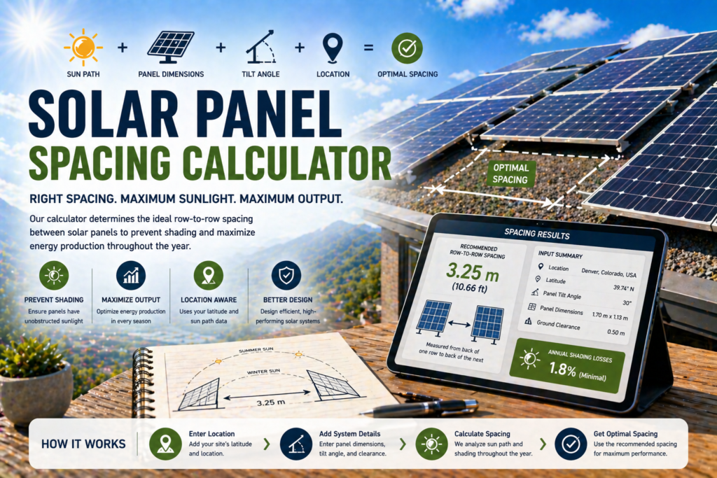
Solar Panel Row Spacing Calculator
Estimate row pitch for repeated, equator-facing solar-panel rows: the distance from the same edge of one row to the same edge of the next. This calculator uses panel length along the tilted surface, tilt, latitude and a winter-solstice solar-time criterion. It is a geometric planning estimate, not a guarantee of year-round shade-free operation.
Distinguish the panel’s horizontal footprint from the clear gap behind it. A pitch of 3.65m does not mean a 3.65m aisle. Nearby objects, nonuniform terrain, unequal mounting heights, access and structural requirements need separate site-specific review.
Choose this tool for row-to-row geometry. It does not calculate mounting-rail span, clamp zones or side-to-side module gaps; use the panel and racking manufacturer’s requirements for those dimensions. Use the Solar Panel Tilt Calculator for a tilt starting assumption and the Solar Panel Output Calculator for a separate energy scenario. Neither transfers a physical layout or shade-loss model automatically.
How Far Apart Should Solar Panels Be?
There is no universal row gap or fixed multiple of panel height. The result depends on the panel’s tilted length, tilt, row-facing direction, design date/time and ground slope. This model assumes rows face the equator, with identical lower-edge mounting heights.
Level-ground winter-noon geometry:
Pitch = L × cos(tilt) + L × sin(tilt) ÷ tan(solar elevation). Clear gap = pitch − horizontal footprint. L is panel length along the tilted front-to-back surface, not mounting height.
For a 1.70m panel length, 30° tilt and 40° latitude, Simple Mode uses winter solar noon: 26.56° solar elevation, 1.47m footprint and 1.70m additional separation. Minimum modeled pitch is 3.17m; a 15% buffer gives 3.65m pitch, or about 2.18m of clear horizontal gap.
Biggest factors that affect panel spacing
- Panel tilt angle
- Panel length along the tilted surface
- Latitude and seasonal sun angle
- Selected winter-solstice solar-time criterion
- Ground-mounted layout and available land area
Solar Panel Spacing Calculator
Calculate minimum and recommended solar panel row spacing using winter sun angle, panel tilt, latitude, planning buffer, and advanced terrain assumptions.
Assumption: equator-facing rows, panel length measured along the tilted surface in the front-to-back direction, identical lower-edge mounting heights, and solar time (not clock time). Positive terrain slope means uphill moving toward the next row. Equal bottom mounting heights cancel from row spacing calculations; this input is used only to annotate the schematic. The terrain diagram is illustrative, not a scaled slope survey. At the equator, winter uses the December-solstice side for this planning approximation. Final layouts need site-specific shading, roof, structural and electrical reviews.
Tools for Measuring and Planning Your Solar Panel Layout
Affiliate disclosure: As an Amazon Associate I earn from qualifying purchases. If you buy through these links, I may earn a commission at no extra cost to you.
Bosch GLM 50 C Laser Distance Measure
A laser distance measure for checking available installation space and marking out distances between planned panel rows. Take measurements from consistent reference points when comparing your layout with the calculator results.
Click for the latest price.Klein Tools 93LDM100C Compact Laser Distance Measure
A compact measuring tool for checking panel positions, clear gaps and available installation dimensions. Useful when transferring your planned row pitch to the site.
Click for the latest price.Anbte Aluminum Solar Panel Mounting Rail and Clamp Kit
An aluminum rail and clamp kit for mounting solar panels. Compare the kit contents, panel frame dimensions, roof type and mounting requirements with your own installation before choosing hardware.
Click for the latest price.Klein Tools 935DAG Digital Angle Gauge
Check the installed panel tilt against the angle used in your row-spacing calculation. Verify mounting surface alignment and follow the gauge instructions.
Click for the latest price.Check current product specifications, compatibility, price and availability on Amazon. Measuring tools support layout planning; mounting hardware must suit your panels, structure and installation requirements.
Continue Planning After Panel Spacing
After a geometry comparison, explore tilt assumptions, separate solar production and energy sizing. Related calculators do not automatically import this row layout or validate an installation.
Solar Panel Tilt Calculator
Compare latitude-based annual and seasonal tilt references before testing row geometry.
Solar Panel Angle Calculator
Compare true compass direction and tilt references; this spacing model assumes equator-facing rows.
Solar Panel Output Calculator
Estimate production under separate inputs; row geometry is not imported.
Solar Array Planner
Estimate array power from daily demand; this does not arrange physical rows.
How to Use the Solar Panel Spacing Calculator
Use Simple Mode for a level-ground winter-noon comparison. Advanced Mode adds terrain slope, mounting-height illustration, a longer solar-time window and a planning goal. Outputs remain geometry estimates; they do not calculate annual shade losses, roof setbacks or installation clearances.
Enter Tilted Panel Length
Enter the front-to-back length measured along the tilted panel or row surface, not the height above ground. Select Metric for metres or Imperial for feet. For multiple modules stacked in the tilt direction, use the total relevant sloping row length.
Set Tilt and Latitude
Enter tilt above horizontal and latitude, using negative latitude in the Southern Hemisphere. Rows are assumed equator-facing: south-facing in the north and north-facing in the south. The optional city lookup is a convenience; verify the latitude. The tool has no row-azimuth input.
Choose the Advanced Criterion
Simple Mode uses winter solar noon on level ground. Advanced 10am–2pm uses the 10am endpoint; 9am–3pm uses 9am, with symmetry assumed. These are solar times, not local clock times. Positive slope rises toward the next row. Equal lower-edge mounting heights cancel in the spacing equation; the height field changes the illustration, not pitch.
Review the Spacing Result
Review minimum pitch, buffered recommended pitch, footprint and additional separation. Balanced applies the entered buffer; Compact caps that buffer at 10%; Maximum winter applies at least 25%. None is an annual energy optimization or shade-free guarantee. If the chosen winter sun is below the horizon, the tool reports that a finite result is unavailable.
Understanding Your Solar Panel Spacing Results
“Minimum” is the modeled same-edge row pitch for the selected geometry, before buffer. “Recommended” is a buffered pitch, not a code clearance or guaranteed installation dimension. Convert to a clear horizontal gap by subtracting the panel footprint from the pitch.
Minimum Row Spacing
Minimum pitch includes both panel footprint and additional separation. The percentage buffer is applied to the full pitch. Subtract the same footprint from recommended pitch to obtain the buffered gap; do not add another panel length to the result.
Winter Shadow Length
“Winter Shadow” is the extra separation beyond the panel footprint for the modeled row-to-row condition. It is not the complete shadow to bare ground from an elevated panel, nor proof of clearance at every winter time. The schematic is illustrative and not vertically to scale.
Why Spacing Matters
Solar panels connected in a string can lose significant output if even one panel is partially shaded. Proper spacing helps keep panels fully exposed to sunlight.
Interpret the Inputs Before Choosing a Layout
- Use panel length along the slope, not mounting height
- Read pitch and clear gap as different distances
- Check the selected solar-time criterion and hemisphere
- Verify access, roof and structural requirements separately
How to Calculate Solar Panel Row Spacing
Let L be the sloping panel length and β its tilt above horizontal. Vertical rise R = L × sin β; horizontal footprint F = L × cos β. With equal lower-edge heights and level ground, winter-noon pitch P = F + R ÷ tan α, where α is the selected solar elevation.
At off-noon times, the tool uses the sun’s component perpendicular to the rows rather than treating the entire shadow as a rearward shadow. Its slope model solves P = (F × z + R × q) ÷ (z + q × tan s), limited to at least F. Here z is the sun-vector vertical component, q its rearward horizontal component and s the uphill ground angle toward the next row.
Solar Panel Spacing Formula
Clear horizontal gap = modeled pitch − horizontal footprint. Buffered pitch = modeled pitch × (1 + selected goal’s effective buffer fraction). Equal mounting heights cancel; adding bottom clearance to the shadow would count a height difference the model does not have.
The winter declination is fixed at ±23.44° for the selected hemisphere. At latitude zero the model uses the December-solstice side. It checks the selected endpoint, not an annual path, hourly weather sequence, horizon profile or arbitrary row azimuth.
This page’s displayed GCR is horizontal footprint ÷ recommended pitch. Some other tools define GCR using sloping row/module length ÷ pitch, so their numeric values differ. Check the definition before transferring a value; see Sandia PVPMC’s pitch and GCR explanation. This reference does not validate the present calculator.
Key Factors That Affect Solar Panel Row Spacing
- Tilted panel/row length and equal lower-edge heights
- Panel tilt angle
- Latitude and lowest winter sun angle
- Selected winter solar-time criterion
- Available ground space and layout goals
Example Solar Panel Spacing Calculation
Reproduce the Simple Mode default in Metric units: panel length 1.70m, tilt 30°, latitude +40° and buffer 15%. Simple Mode uses level ground and winter solar noon. The following distances are horizontal row geometry, not access requirements.
Example Solar Installation
- Panel length along tilted surface: 1.70 metres
- Panel tilt angle: 30°
- Installation latitude: 40°
- System type: Ground-mounted solar array
Step-by-Step Calculation
1. Vertical rise R = 1.70 × sin 30° = 0.85m.
Horizontal footprint F = 1.70 × cos 30° = 1.472m.
2. Winter-noon solar elevation = 90° − 40° − 23.44° = 26.56°.
3. Extra separation = 0.85 ÷ tan 26.56° = 1.700m.
4. Using unrounded rise and footprint, minimum pitch ≈ 3.173m.
Apply the 15% buffer to unrounded minimum pitch: recommended pitch ≈ 3.649m. Subtract unrounded footprint to obtain clear horizontal gap ≈ 2.176m. Round only the final displayed results.
Final Recommended Row Spacing
For this example installation, the recommended spacing between solar panel rows would be approximately:
- Minimum pitch: 3.17m; recommended pitch: 3.65m
- Extra separation before buffer: 1.70m
- Buffered clear horizontal gap: about 2.18m
The displayed projected-footprint ratio is 1.472 ÷ 3.649 × 100 ≈ 40.4%. A different latitude, solar-time window, slope or goal changes the result. This example does not establish annual energy yield or an approved site layout.
Did You Know?
The Model Assumes Equator-Facing Rows
Here rows face south in the Northern Hemisphere and north in the Southern Hemisphere. This is a model assumption, not a site-specific optimum. The calculator has no orientation input for east-west or other row-facing directions.
East and West Panels Still Work Well
East-west and other orientations require different shadow geometry. Do not treat an equator-facing spacing result as valid for another orientation without a separate assessment.
Angle Adjustments Can Improve Solar Output
Changing tilt changes both vertical rise and horizontal footprint. Compare complete pitch and gap results; a higher vertical rise alone does not describe the whole layout.
Solar Tracking Systems Follow the Sun
Tracking arrays change orientation during operation and can use backtracking. This fixed-tilt calculator does not model tracker movement, backtracking or mechanical clearance.
Expert Tips for Solar Panel Row Spacing
Panel spacing is one of the easiest places to make expensive mistakes in a ground-mounted solar design. If rows are too close together, winter shading can reduce output. If rows are spaced too far apart, you waste land area and increase installation costs. These practical tips help you strike the right balance.
Design Around Winter Sun First
Choose a winter time criterion suited to the planning question. Winter noon is not the lowest sun angle of the day; near sunrise or sunset the sun approaches the horizon. A longer modeled window can require more pitch or produce a no-sun result.
Steeper Tilt Usually Means More Space
Steeper tilt raises the rear edge but reduces the horizontal footprint. Compare the complete geometry rather than applying a fixed height multiplier. The result also depends on latitude, solar time and slope.
Land Efficiency Sometimes Matters More
Some systems accept a small amount of winter shading so more panels can fit in a limited space. That can make sense for certain solar farms or properties where available land is the real bottleneck.
Leave Room for Access and Maintenance
Row spacing is not only about shadow clearance. You may also need extra room for walking paths, cleaning access, mowing, snow removal, wiring runs, or equipment servicing.
Use a Site-Specific Final Check
Avoid a universal 2-to-3-times-height rule. Verify the design criterion, obstacles, terrain, access and applicable site requirements. The calculator’s percentage buffer is a geometric allowance, not a quantified shade-loss, snow or maintenance allowance.
Solar Panel Spacing Comparison Guide
These reproducible comparisons use 1.70m panel length, 30° tilt, level ground, equator-facing rows, equal lower-edge mounting heights, Metric units, Balanced goal and 15% buffer. Row pitch is measured between matching edges. The values are model scenarios, not typical installation ranges.
| Latitude | Recommended Pitch | Solar-Time Criterion | Minimum Pitch Before Buffer |
|---|---|---|---|
| +20° | 2.62m | Noon | 2.28m |
| +40° | 3.65m | Noon | 3.17m |
| +50° | 4.98m | Noon | 4.33m |
| +40° | 3.95m | 10am–2pm | 3.44m |
| +40° | 4.62m | 9am–3pm | 4.01m |
Why Spacing Design Matters
The comparison shows how latitude and the selected winter endpoint affect geometric pitch. It does not calculate annual kWh, cost-optimal density or the fraction of shading. Use a time-resolved site model for those questions; see the SAM shading and layout documentation for the distinction between self-shading and external obstacles.
Visual Insight: How Solar Panel Row Spacing Works
Solar panels mounted in rows create shadows behind them when the sun is low in the sky. If the next row of panels sits inside that shadow zone, energy production can drop significantly. Proper spacing allows sunlight to reach every panel during critical production hours.
Morning Sun Position
In the early morning, shadows extend farther behind panels because the sun sits lower on the horizon. Proper row spacing helps ensure the next row still receives usable sunlight.
Midday Sun Position
When the sun is higher in the sky, shadows shorten significantly. Most solar arrays produce their peak electricity output during these midday hours.
Winter Sun Position
The selected winter endpoint is one design criterion. It does not represent every winter sun position or guarantee consistent annual production. The accompanying graphics illustrate concepts, not measured sun paths or scaled installation dimensions.
Key Insight
Check row pitch, actual clear gap and site access separately. A spacing geometry result does not quantify energy lost to shading. Use a site-specific assessment before finalizing a layout.
Planning Your Solar Panel Layout
Solar panel spacing is only one part of a complete solar array design. A well-planned system considers panel tilt, daily energy production, battery storage capacity, and inverter sizing to ensure the entire system works together efficiently.
Once you estimate the correct row spacing, the next step is confirming how much electricity your solar array can produce and how that production matches your energy needs.
Estimate Daily Solar Output
After spacing the panels correctly, estimate how much energy your system can generate each day using the Solar Panel Output Calculator.
Match Production With Energy Use
Calculate how much electricity your home, cabin, or RV consumes with the Solar Power Consumption Calculator.
Size Your Battery Storage
If your system includes battery storage, determine the proper capacity using the Solar Battery Size Calculator.
Complete Solar System Planning
Proper solar panel spacing improves energy production, but the overall performance of a solar power system depends on the balance between solar generation, energy storage, and electricity usage. Planning these components together helps create a reliable and efficient solar setup.
Solar Panel Spacing — Common Questions
Practical answers about solar panel row spacing, shading, winter sun angles, ground coverage ratio, and layout planning for ground-mounted and flat-roof solar arrays.
There is no universal row pitch. This model uses tilted panel length, tilt, latitude and a winter-solstice solar-time criterion for equator-facing rows. Minimum pitch includes the horizontal footprint plus modeled additional separation. Recommended pitch applies the selected planning buffer; it is not guaranteed shade-free all year.
For level ground at winter solar noon, pitch = L × cos β + L × sin β ÷ tan α. L is tilted front-to-back row length, β is tilt and α is solar elevation. Off-noon and sloped-ground cases use the sun’s rearward component and the terrain equation described above. Clear gap equals pitch minus horizontal footprint.
Panel length, tilt, latitude, solar-time criterion and terrain slope determine this model’s geometry. Identical lower-edge mounting heights cancel in the equation. Obstacles, unequal heights, irregular terrain, access and roof requirements need separate review; the percentage buffer does not model those constraints.
Row shading can reduce output, but this tool calculates geometric spacing rather than annual energy loss. The Solar Panel Output Calculator provides a separate energy scenario and does not ingest this pitch or calculate its shading impact automatically. A time-resolved site model is needed to compare layout yield.
This calculator labels horizontal panel footprint divided by recommended pitch as GCR. Other modeling tools may use sloping row/module length divided by pitch, so the values differ by convention. Check definitions before transfer. The Solar Array Planner sizes power from energy demand; it does not determine physical row placement.
Use Simple Mode with 1.70m length, 30° tilt, +40° latitude and 15% buffer. Winter solar noon gives 26.56° elevation, 1.472m footprint, 0.85m rise and 1.700m additional separation. Minimum pitch is 3.17m; buffered recommended pitch is 3.65m and its clear horizontal gap is about 2.18m.
The geometry can inform a preliminary comparison for repeated tilted rows on a level surface with equal lower-edge heights. It does not model arbitrary roof slopes, parapets, obstacles, setbacks, structural loading or installation access. Flush-mounted or differently oriented roof layouts need their own assessment.
This tool does not prescribe maintenance aisles or fire-access clearances. Determine required access, cleaning, snow management and service space from the actual site and applicable requirements, then compare those dimensions with the clear gap rather than with pitch. No universal 0.6–1.0m allowance is established here.
Related Tools for Solar Layout and System Optimization
These tools help refine wiring, efficiency, overall system design, and long-term value without duplicating the main next-step links above.
Solar Wire Size Calculator
Explore preliminary voltage-drop and current assumptions; verify installation requirements separately.
Solar Panel Efficiency Calculator
See how panel efficiency affects the value of an optimized spacing and layout strategy.
Complete Solar System Calculator
Compare a separate off-grid energy-sizing scenario.
Solar Payback Period Calculator
Explore financial assumptions separately; the tool does not derive savings from row pitch.